The SPRED spectrometer used on the ASDEX-Upgrade tokamak at the Max-Planck Institute for Plasma Physics in Garching is a workhorse spectrometer for finding impurities in the plasma. Built by a now-defunct exterior firm, the angle of the grating (critical for the proper scattering the light) became misaligned over its long operational lifetime. It became my job to understand this spectrometer and return it to operation as best I could.
Impurities are defined as elements in the plasma outside the main atomic species (which is often an isotope of hydrogen). SPRED stands for Survey, Poor Resolution, Extended Domain and it is used to measure a wide, generally hard-to-characterize wavelength space. These other impurity elements are heavier with more protons and consequently have tighter bonds with the orbiting electrons. High temperature plasmas will collide with bound electrons which can change their energy level or liberate them entirely. These electrons will transit various energy levels leading to high energy photons different than those emitted by hydrogen.
This spectrometer has existed on the ASDEX-Upgrade from the beginning of its operation in 1991. It and others like it derive from the original built in 1982 by Professor Fonck at Princeton for the PLT tokamak. A specially designed grating preferentially reflects and focuses higher energy photons (light) while discarding other light wavelengths. The SPRED spectrometer measures impurity line emission in what is known as the ‘Extreme UltraViolet’ (EUV) or the ‘Vacuum UltraViolet’ (VUV) range using two separate cameras and gratings. These ultraviolet photons are more similar to X-rays than the UV rays which damage our skin in the sunlight. They cannot penetrate deeply through most materials or gasses (hence the name vacuum UV), and their measurement requires special detectors (deep-depletion/ back-thinned CCDs or MCPS) placed under vacuum.
This project in total was a tough problem as it had the following large issues: it had no major documentation of its designs (outside the specification of the gratings), there was no way of accurately calibrating the grating angle in place, the spectrometer is one-of-a-kind, and the system could only be fully verified for operation after complete installation at the very end (i.e. under vacuum). These problems were systematically retired through the following steps:
- Analysis of previous operation
- Reverse engineering the spectrometer with minimal disassembly
- Designing and implementing a system for angular calibration of a EUV/VUV grating
- Designing and building fixtures for in-place verification
- Analysis of spectrometer operation
Analysis of previous operation
In my case, the ASDEX-Upgrade SPRED spectrometer had been designed and built by an outside German company. They had been contracted to hand over the design drawings along with the spectrometer. However, this company did not comply with this after the spectrometer delivery. Nevertheless, it worked as advertised and the issue was dropped. In fact, the spectrometer operated as designed for over 20 years without major issue with the original components. However, at some period of time the wavelength range that was measured began to shift. A student thesis around this time was able to correct for this issue and still yielded viable and interesting results. The previous micro channel plate (MCP) system used for measurement was replaced by more modern intensified CCDs which have become the norm for these styles of measurements.
Finally, a the change in the angle of the second grating was large enough to ruin the spectra entirely. At the time it was not known that the angle was the cause in the failure, so attempts were made to diagnose the issue. Due to the relatively bullet-proof nature of its operation, it had been minimally opened for inspection during its years of operation. A new CCD camera was purchased to replace the old MCP and it was finally opened to inspect its interior. At the time of my introduction, the exterior vacuum housing had been opened, and the old camera system completely removed. At this point, I became the principal investigator in diagnosing and repairing this issue, while integrating the new camera into operation.
Reverse engineering the spectrometer without complete disassembly
Reverse engineering of products, processes and codes have become more and more commonplace worldwide. Often considered malicious, such engineering is can actually be beneficial is restarting and recovering previously used methods and understanding. A great example from recent memory is the possible return of the American F-1 rocket engine for possible use by NASA in the STS program. The shift in the American program to other fuels left little hands-on expertise with hydrocarbon-based systems, and a team by NASA set out to reverse engineer it. In a similar situation, I too was responsible to understand the engineering necessary for a previous design and attempt to improve on it. However, a further complication existed in comparison to others, in that the system is one-of-a-kind, requiring an even more conservative approach.
Unlike the rocket engine, the problem was not to characterize the entire product or understand facets of the design, but it was to only to calibrate the grating angle. The disassembly of a precision mechanical component has some chance of irreparably changing it. The spectrometer geometry is principally important for a spectrometer for the focus, sagittal and meridonal planes and affect the overall light intensity. Understanding the optics will change the optics. In other words, changes in disassembly also makes the angular correction a moving target: the more I change, the more that could unknowingly also change the optics. While this is likely not a large issue for a properly designed piece of hardware, there is no assurance that fact is true in this case. It is possible that motivations behind design choices stay unknown until its too late, and that eventuality ruins the spectrometer. As such, a minimally invasive procedure was most important, even at the cost of precision in the correction.
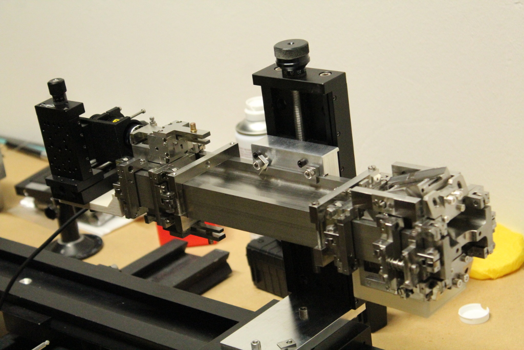
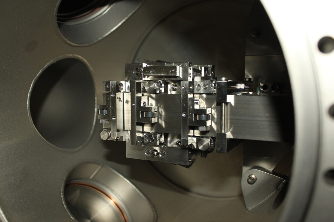
The calibration procedures and equipment for the spectrometer needed to be inferred and redeveloped. As a consequence, only the most important components were modelled and measured. In the initial picture of a CAD model shown at top is structure of the spectrometer core and grating mounting structure. As can be contrasted by the image of the core below, the forward section which collimates the light is completely neglected.
While even after the completion of the calibration, I am still puzzled by certain design choices of the manufacturer. Its not Design choices and measurements are often at whole units, units of 10 or a reasonable fraction (for metric). This makes clear probably 90 percent of distances or clearances, but then there are blind holes, random screws, quirks in the overall structure which can be completely hard to justify. The difference between a important versus unimportant constraint can be difficult.
Using the CAD model developed by over a month’s worth of measurement, the recalibration could begin. Also by knowing the failure mechanism, I could design both the necessary calibration equipment and improvements to mitigate the problem in the future.
Designing and implementing a system for angular calibration of a EUV/VUV grating
The failure in maintaining the angle was clear from the beginning, but methods for fixing it took much longer to develop. The grating sat within a cylindrical mount with two posts on either side on the major axis of symmetry. These posts mated to the spectrometer rail through bearings which in turn allowed free rotation of the grating. The angle was fixed by friction around this small post, with a clothes-pin like metal bar, which could be manipulated with a small screw. Tightening this screw (which connects the ends of the fork) reduces the size of the hole and puts friction on the post. This friction was insufficient to hold the post over the 20+ years of operation.
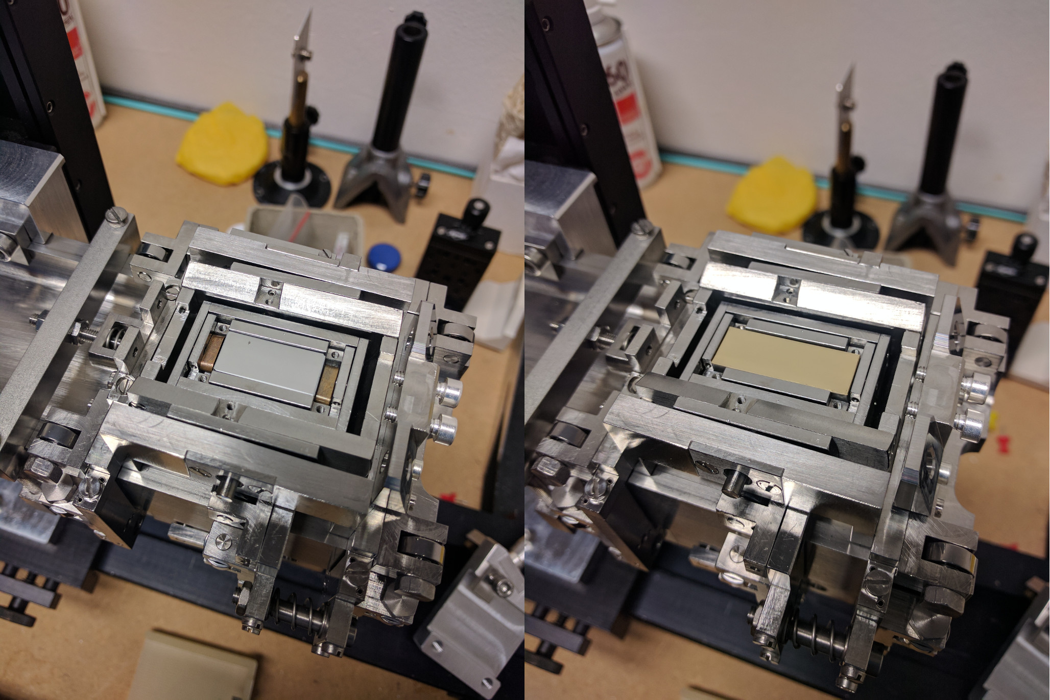
Additional methods for fixing the grating’s rotation were necessary to prevent the future drift in the angle. However, due to the lack of knowledge and due to the uniqueness of the parts, it was not feasible to modify the existing pieces without further misaligning the optics. Two screw holes behind the cylinder (added for some unknown reason) allowed for an additional part to be installed. This part was tangential to the axis of rotation and to the large cylinder face. A set of screws would then provide friction to the outside of the cylinder and have a larger torque due to the larger radius at which it was applied. These features can be seen in the figure above to the right of the grating.
Other pieces which were not permanently attached were also developed. These were used for the angular calibration. A long lever arm was attached to the main rotation axis previously described. At the end sat a micrometer screw perpendicular to the arm. The lever arm translates the subtle movements in the micrometer to changes in angle (through the tangent). The longer the lever arm, the smaller change in angle for a given change in the micrometer screw. While this allows for the precise adjustment of the angle, it does not accurately determine the angle on its own. Precise trigonometry was also necessary to solve for the angle, requiring a secondary system for this determination.
A laser system was set onto an optical rail with the spectrometer core (as seen in an above photo). In tandem with a precise inclinometer (accurate to .002 degrees), the angle of the laser and the spectrometer core were determined. At a precisely known distance from the spectrometer the laser was fixed. The emitted light was directed through the pinhole, reflected off the grating and projected onto the wall. The wall was sufficiently far away to make a triangle set by the reflected light, the initial laser angle and the wall. This triangle, over a meter on each edge, was fully determined by the angles and distances measured beforehand. A large poster of 1mm grid paper was used to compare the initial laser beam spot (without the spectrometer) and laser spot’s reflected position, giving an accuracy better than 1mm/1m. The long distances used, just like the micrometer adjustment, made for a precise measurement of the angle. By using the precise measurement and the precise adjustment device, it was possible to increase the accuracy of the angle measurement significantly. Initial estimates using experimental data found that the angle of the SMF grating was properly set to within .2 degrees.
Fixtures for in-place verification
After the precise calibration, it was unknown what was necessary to preserve the alignment in reinstallation. Again, a conservative course of action was taken. Two shrouds were 3D printed which went over the entire grating holder to prevent bumps and accidents from causing any changes. However, that is not sufficient to guarantee proper operation after reinstallation in the vacuum vessel. A secondary system needed to be developed to set the cameras to the proper focus and wavelengths. This is backwards from visible camera systems, where the optics themselves are often adjusted to improve image quality.
As can be seen in the above figure, there was simply not enough room to put in an optical rail or any other device with enough accuracy for the focus and wavelength adjustments. Again, two avaiable screw holes in the spectrometer were re-used. When reassembled, these two screws hold the differential pumping section to the front of the spectrometer core. This was ideal as they are located near the main conflat flange at the front of the spectrometer, opening widely to the outside world. This mounting point was repurposed to hold a laser or LED for the initial camera wavelength and focus calibration. Using 3D printed parts and precision optical adjustment tables, the light source position could be adjusted and fixed as necessary to the front of the aperture.
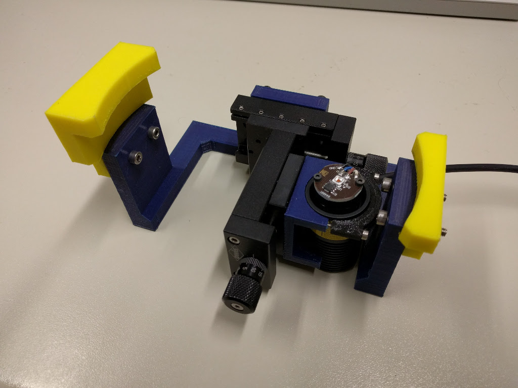
The light from the the LED and laser, after passing through the aperture and reflecting off the grating, are sent to the image plane. On this end another fixture was built to set the focus and wavelength (essentially the position) of the camera. As with the laser/LED mount, the secondary fixture was attached to the exterior vacuum vessel. This point is how the cameras are attached to the spectrometer. The calibration fixture also used precise optical tables to adjust a visible camera CCD. The CCD was used to find the 0th order focus position with proper offsets such that the wavelengths of interest could properly imaged by the UV camera.
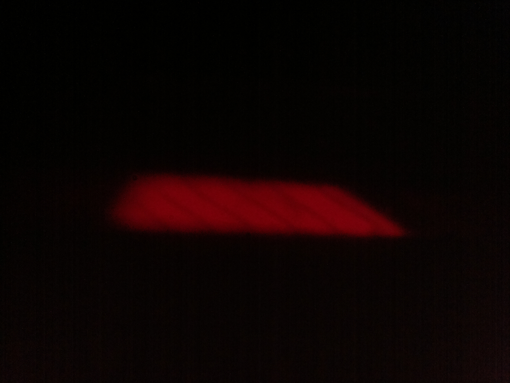
An example of the focus calibration using the 0th order (visible red light in this case) is shown above. The CCD used was a regular Raspberry Pi camera with the lens removed. The exposed CCD could measure and set the position with great accuracy without too much effort. Its small size and simple mounting design made the fixture design relatively easy. The acquisition and visualization of the CCD output comes standard in the Raspberry Pi operating system. Finally, the small pixel size (on the order of micrometers) also made precise adjustment of the camera position identifiable and reproducable.
However, before this calibration system could be used, the core of the spectrometer had to be returned to its initial position. This position is very important as the location of the imaging planes are directly related to the mounted position of the spectrometer core. If this were not properly set, it could cause the focus to vary across the CCD. After having successfully reproduced the previous position within a .5mm it was assured that alignment of the new Princeton Instruments cameras could proceed.
Analysis of spectrometer operation
The two Princeton Instruments X-100B cameras were installed and the whole vacuum system was systematically reassembled. Unfortunately, the previous focusing the 0th order (regularly reflected light) using red light did not guarantee that the 1st order scattered light was also in focus. A secondary calibration was necessary to fully focus the camera. For EUV and VUV spectrometers it is important to have and EUV/VUV light source for calibrations.
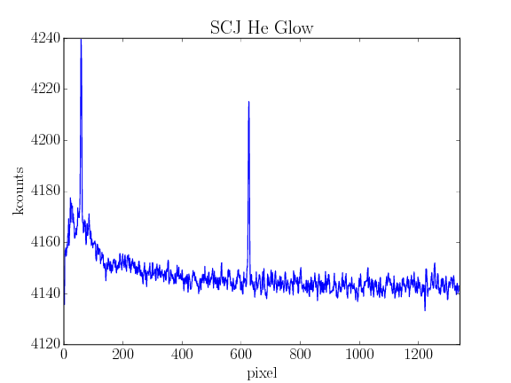
The available light source at ASDEX-Upgrade is a Helium plasma which creates several strong and easily identifiable emission lines at specific wavelengths. In the UV, these were used to find the wavelength of the spectrometers, and set the proper focus (by minimizing the width of the line). This older system uses at 10kV 10mA power supply to energize a thin helium gas using a square antenna.
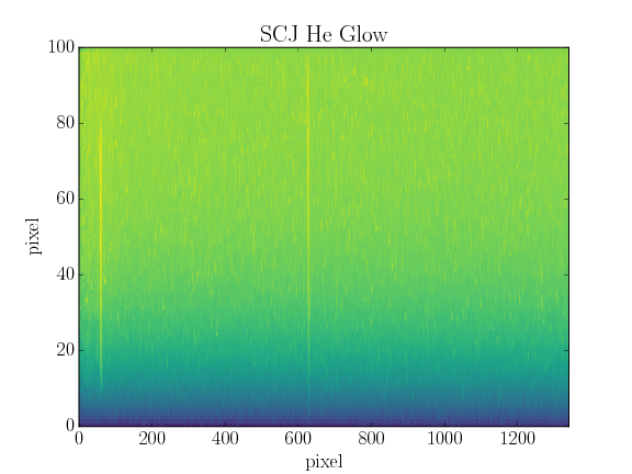
The CCD sensor of the spectrometer cameras are a 2d arrays which are summed in one direction to make a 1d spectrum. The width of any observed photon line is also dependent on the aligment of wavelength axis, and the binning direction of the CCD. When they are not perpendicular, the intense peak in the spectrum can be blurred to neighboring bins. Simply, the light will show up as other wavelengths. As such, the rotation of the camera had to also be set and calibrated. As shown in the figure above, the camera was rotated to best align these two. In the end 3 degrees of freedom in the cameras had to be determined (two positional, one rotational).
Conclusions
With all of this work, the spectrometer (with the two gratings and two cameras) was returned to service. The understanding, fixing and calibration of a unique instrument (truly unique, as the only in the world) was a daunting task. However, with conservative planning often with significant engineering it became possible. With a slow and careful approach it is possible to fix most things, however it is truly a question of time and effort.