I designed and built equipment necessary for Raspberry Pi Cameras to operate in the difficult environment of tokamaks. These cameras faced high magnetic fields, intense radiation bombardment, and substantial heat excursions. These simple and low-cost systems were able to outperform similar older systems at a dramatically reduced price with simpler implementation. While the operation of the Raspberry Pi camera is well-documented and straight-forward, this new equipment interfaced with the computer, electrical and mechanical systems of the Alcator C-Mod tokamak.
This required the following:
- Coding an interface with the experimental data system
- Design and manufacture of camera mounting structure
- Optimization of the optics for individual views
- Isolation of the electrical triggering
- Placing power supplies away from high magnetic fields
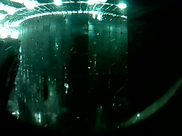
The end result of this work can be seen in the spectacular conclusion of the plasmas (known as a ‘disruption’) shown both in the video (which I uploaded to Youtube) and the introductory image at the top of the page. These highlight the camera’s robustness and exhibits the ability of such simple systems to collect such unique and interesting images.
Depending on the settings and optics, it can take high quality 5MP pictures 10 times a second all the way to 640x480 resolution at 90 frames per second. The picture and video are from these two ends of this acquisition spectrum. Limitations in the lenses in this case reduce crisp quality of the full images, but are still spectacular in their own way. In the end, I installed four of these cameras at various locations around the tokamak, each of which yielding a unique perspective on the world of high-temperature plasma physics.
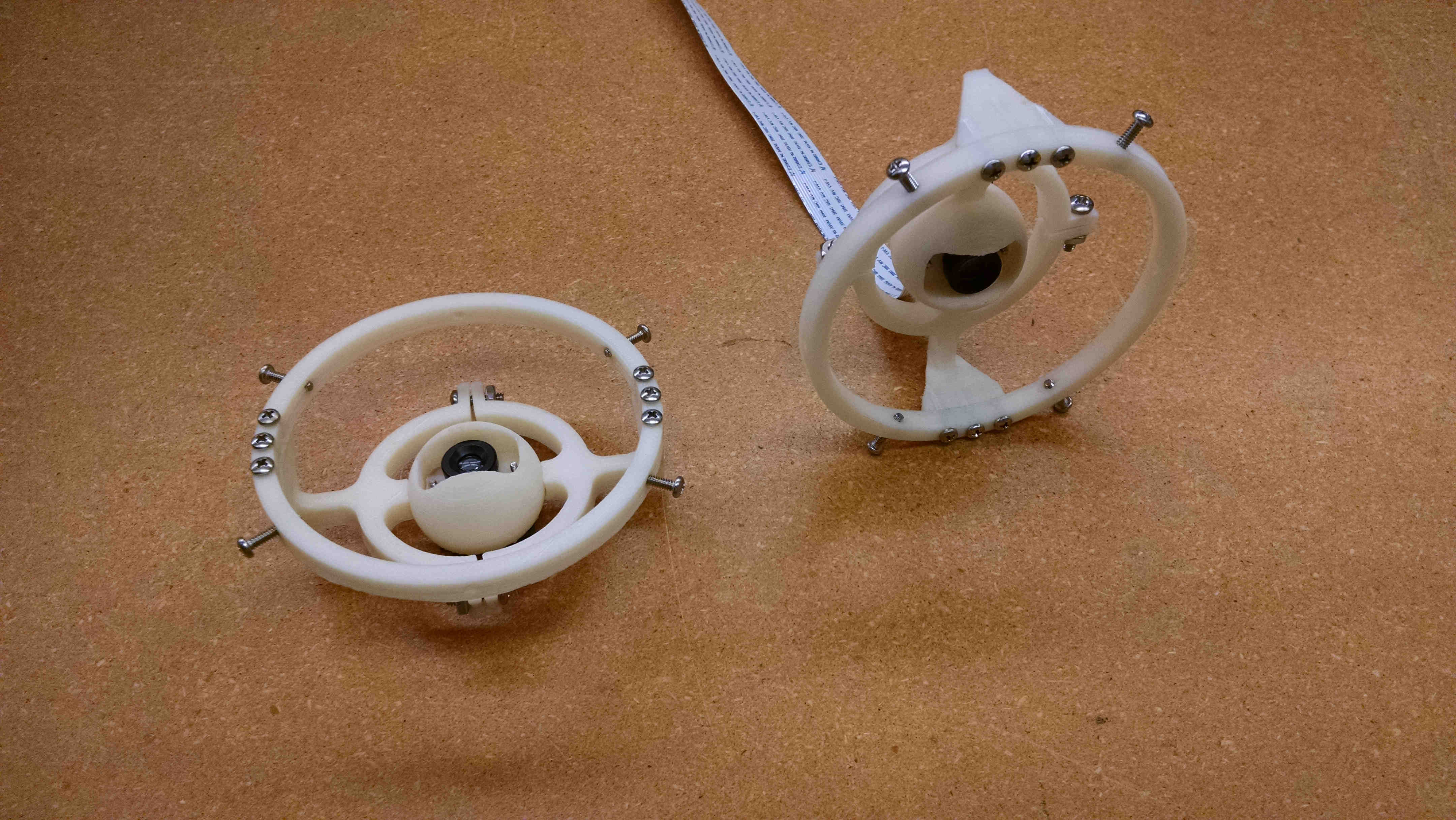
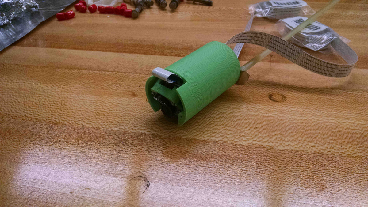
Design and manufacture of the camera mounting structure
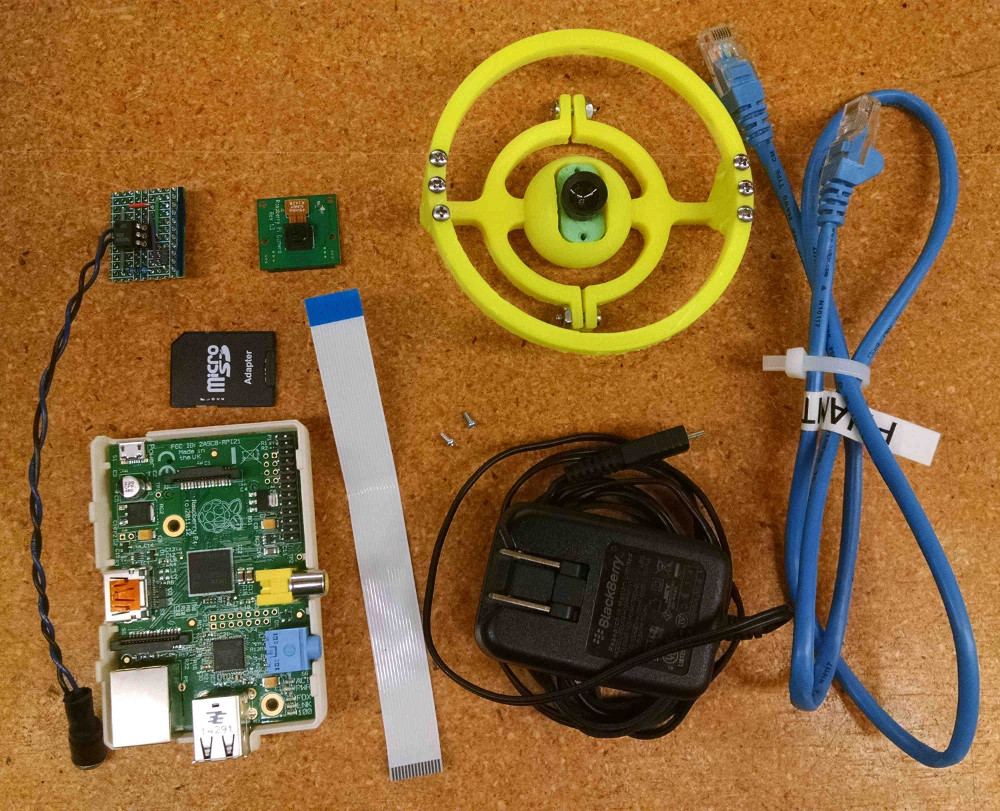
Tokamaks are vacuum chambers which are limited in space due to the surrounding magnets and supporting structure. The extreme mechanical and electromagnetic environment leaves little room to view the plasma, and so the optimal placement of cameras is key. The camera with optics is placed on a printed circuit board ( PCB) which then can be mounted using a typical S-mount. This small size package is ideal for the tight volume available.
Optimization of the optics for individual views
The standard lens on the Raspberry Pi is ideal for distances greater than one meter with a wide field of view. The uses of this camera on tokamaks vary from fisheye views to telescopic/focused views, requiring alternate optics. Luckily the PCB was designed to accept other optics and the choice depends on the desired view. Outside of the optics, the mounting structure can be easily 3D printed and tapped.
The standard optics for the Raspberry Pi camera can be removed with a set of pliers, which exposes the underneath CCD. The screw holes on either side of the CCD on the PCB can mount M12 optics. The optics themselves are sized to fit a M12 hole with .5mm pitch (which is very fine. For installing lenses in 3D printed parts, a tap can be bought on Amazon or Aliexpress). The M12 optics are typical of CCTV systems and can be easily purchased in all sort of shapes and sizes from manufacturers on Alibaba. The low cost (less than $20 a piece) and ease of interfacing with the manufacturing makes acquiring optics easy. The hardest part is getting the company representatives to leave you alone afterward.
This was my first foray into buying direct from a factory and I now understand the powerhouse that is Chinese manufacturing. Shenzhen is not just for cheap knock-offs, but you have access to ravenous sellers willing to sell you just about anything. If you ever want to build a device with a electrical or mechanical interface, that is where to get it. I think it is inevitable that the creative side of those builders will lead to the next ‘must have’ or game-changing products.
To set the focus, you simply screw in and out the optics while the camera is running. When it is in focus, use superglue to hold in place. Typically the M12 lens focus are not very precise, where the quality of focus is usually specified in ‘megapixels’ (typically less than 5MP). Higher quality lenses are often it is quoted in lines/mm, but the other quality standard is generally used for lower quality CCDs and sensors. Ultimately the quality of these lenses limit the clarity of full images taken but is relatively inconsequential for lower quality video. The initial image of this page shows the limitation in quality of a full 5MP image. A newer Raspberry pi camera is capable of taking 8MP images but are of limited use with these optics.
Isolation of the electrical triggering
If there is anything I’ve learned while doing circuit testing is that both capacitive and inductive coupling of circuits are the most annoying and most present performance limitation for a circuit. Capacitive coupling generally leads to substantial noise affecting the high-frequency capability of circuits and can be reduced with proper shielding and distance. The other, inductive coupling, is discussed much less frequently. Inductive coupling is often seen known by another name in specific circumstances - a ‘ground loop’. Ground loops occur when two grounding points are at different potentials, leading to undesired noise between the two points. This has a surprisingly awesome write-up of ground loops on wikipedia that I recommend.
In the case of the Camera on a tokamak, it is vital that the camera is told to start acquiring images a set time, given by a centralized trigger signal. This 5V electrical signal needs to be sent to the camera, which can be easily done through the Raspberry Pi GPIO. However, the ground of the triggering signal generator and the ground of the camera are separated. The high magnetic fields about the tokamak with the large separation of the grounds leads to significant magnetic flux. This magnetic flux could lead to EMF potentials which could harm the camera.
Electrical isolation of the triggering system from the camera is possible through the use of an ‘opto-coupler’. The triggering circuit connects to the CAMAC triggering board via a 2-pin LEMO, which was standard at the PSFC. The Pi’s side uses pins 4,6 and 8 to get 5V, a ground, and a GPIO pin all of which are close together. A simple pull down resistor and a current limiting resistor for the diode are the only other needed parts.
Placing power supples away from high magnetic fields
One of the first posts I read early on in this project was about the use of a Raspberry Pi camera in an MRI machine. In most cases, the magnetic susceptibility of an electronic device is dependent on the use of inductors, whose operation is dictated by storing magnetic energy. Externally applied magnetic fields can induce voltages in the circuit or can saturate the inductor’s metallic core (depending on the inductor) both of which can impact its operation. A Raspberry Pi has inductors in two places: the ethernet 10/100T port and in the power supply. In both cases, the easiest solution is to shield the equipment and move it far from the intense magnetic field.
Inductive coupling to the tokamak’s magnetic field is inevitable, the question is to what degree. The Raspberry Pi uses a micro USB connector which was the most common connector for non-Apple smart phones (which is actively being replaced by the USB Type-C). Most small commercial 5V power supplies made for phones use flyback converters (which have inductors) to transform the AC voltage to the necessary 5V DC.
Interestingly, the very intense magnetic field of tokamaks (in the toroidal direction) are very well contained by the toroidal magnetic field coils. The separate coil which induces a current in the plasma creates a dipole field which spreads broadly in a well known way from the tokamak. If both the Raspberry Pi and power supply are out of the toroidal field coils, it is this field which affects the circuitry. The power supplies needed an additional 2 or 3 meters radial distance from the tokamak to insure operation during an Alcator C-Mod plasma. The inductors within the ethernet connector were never a large issue, as the camera only really needed to communicate after the plasma had ended (and magnetic field had been removed).
As a point of note, the camera head is rather impervious to the magnetic field and was operating reliably in magnetic fields of 5 Tesla. The data from the camera is communicated digitally using a 20 pin ffc ribbon cable and it is robust even under radiation and intense temporal changes in the magnetic field. The camera itself can then be separated from the Raspberry Pi and power supply by distances of several meters (though distances longer than 2 meters were not tested). Again, purchasing it directly from China might allow for some really interesting and low cost use.
Coding an interface with the experiment data system
The camera by design is meant for a layman to used for plug-and-play projects. The camera can be controlled using a number of programming languages with various APIs including Python, bash and C/C++. From frame rates, to exposures, to white balance, all parameters are controlled through the API to the underlying SDK for the camera interface. Due to my familiarity and relative ease in debugging, Python was used to interface with the experimental data system, which also has a native Python API.
Alcator C-Mod, and most other tokamaks in the United States (and some abroad) use MDSplus to control tokamaks and store experimental data. It has APIs written in a number of languages, with the Python implementation being one of the more expansive and well documented. The MDSplus system is capable of sending broadcast messages over a network to prepare various equipment for a synchronous trigger. A daemon is used to wait for a preparation message which activates a script to set necessary parameters and wait for the trigger pulse. Using the previously described triggering (through the Raspberry Pi GPIO), the camera can also be triggered synchronously.
Before the triggering, a prescribed set of parameters are loaded to the camera (such as the length of the video, quality and frames per second) and the program sets to wait on the GPIO trigger. After the triggering, the file is transferred to a main file server and the video is transformed into a individual black/white intensity images. These images are stored as 8-bit byte data in the MDSplus data structure for analysis.
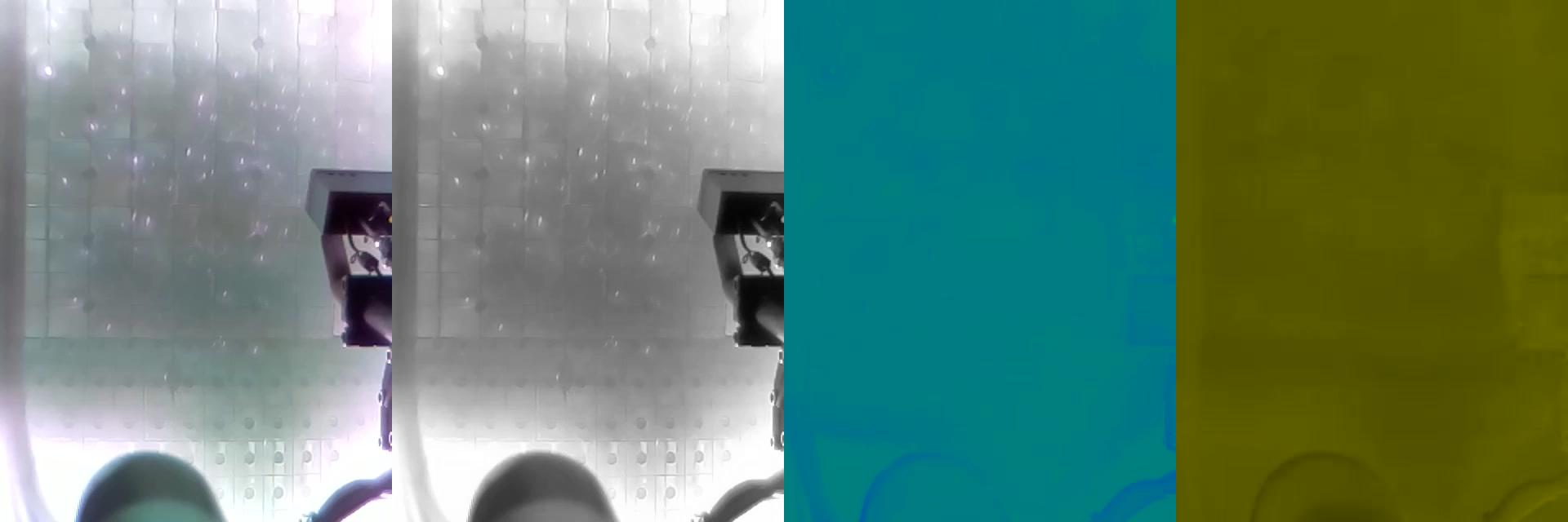
Conversion from video to the intensity data is not as straightforward as would be originally imagined. The video data is originally in mp4 format, which is not intensity data. However, there is a standard format which contains a straightforward output to intensity, it is known as the YUV format. The original purpose was to be able to encode color data while preserving the capability of black-and-white televisions. The camera data was processed from a mp4 video to a YUV420 (where 420 describes the ratio of bits of the various channels). This is then converted into the byte data to be stored efficiently for analysis by the data system.
In the example figure, the various channels of color and luminance are shown for another C-Mod camera image. As human sight is more keyed on intensity (more rods than cones in the eye), correspondingly the resolution of the color channel images are noticibly worse than the black-white image. The sparkling observed are from small pieces of Calcium Floride going into the plasma. The lack of variation in the other channels shows that the intensity data is most interesting for analysis.
The codes are available on my GitHub, just shoot me an email about any questions!